AWS Network Load Balancing & Failover: Install the SafeKit farm.safe Module
High Availability Quick Installation Guide for AWS
This guide explains how to set up a farm cluster for AWS using SafeKit, ensuring network load balancing and automatic failover.
For help, you can use SafeKit AI 🤖.
1. Overview
- Architecture: Implements a scalable, multi-node load-balanced farm with a virtual IP address.
- High Availability: Features automatic health monitoring and seamless failover to ensure service continuity.
2. Installation
- Software: Install the SafeKit engine on all servers.
- Module: Download the pre-configured
farm.safeapplication module.
3. Configuration
- Web Console: Configure the AWS farm cluster.
- Monitoring: Start monitoring and protecting the AWS application.
SafeKit High Availability Limitations
| Limit / Requirement | Reason & Impact | Recommended Alternative |
|---|---|---|
| Replication size: A few TBs |
Resynchronization time after failure (step 3):
|
|
| File count: < 1,000,000 files |
|
|
| Failover capacity: ≤ 32 VMs |
|
|
| Network architecture: LAN/VLAN network between remote sites |
|
|
Overview of the SafeKit / AWS solution
The solution is described here: 💡 SafeKit: Amazon AWS Load Balancing & Application High Availability Farm Cluster.
Installation of the SafeKit / AWS solution on Windows and Linux (farm.safe)
Configuration of the Amazon AWS load balancer
The load balancer must be configured with a virtual IP address.
And the load balancer must be configured to periodically send health packets to nodes.
For that, SafeKit provides a health check which runs inside the nodes and which
- returns OK when the farm module state is UP (green)
- returns NOT FOUND in all other states
You must configure the Amazon AWS load balancer with:
- HTTP protocol
- port 9010, the SafeKit web server port
- URL /var/modules/farm/ready.txt (if farm is the module name that you will deploy later)
For more information, see the configuration of the Amazon AWS load balancer.
Do not configure a virtual IP address and load balancing rules at step 4 in the step by step configuration below. The virtual IP address and load balancing rules are already set in the Amazon AWS load balancer. Setting a virtual IP and load balancing rules at step 4 is useful for on-premise configuration only.
Configuration of the Amazon AWS network security
The network security must be configured to enable communications for the following protocols and ports:
- UDP - 4800 for the safeadmin service (between SafeKit nodes)
- UDP - 4803 for the heartbeat inside the farm module (between SafeKit nodes)
- TCP – 9010 for the load-balancer health check and for the SafeKit web console running in the http mode
- TCP – 9001 to configure the https mode for the console
- TCP – 9453 for the SafeKit web console running in https mode
Package installation on Windows
-
Download and install the free version of SafeKit on 2 Windows nodes.
Note: the free version includes all SafeKit features. At the end of the trial, you can activate permanent license keys without uninstalling the package.
-
Upon completing the package installation, select Set console credentials and firewall rules now and configure a password for the admin user of the SafeKit console.
Set the same password on all nodes.
-
Exclude from antivirus scans C:/safekit/ (the default installation directory) and all replicated folders that you are going to define.
Antiviruses may face detection challenges with SafeKit due to its close integration with the OS, virtual IP mechanisms, real-time replication and restart of critical services.
Package installation on Linux
- Install the free version of SafeKit on 2 Linux nodes.
Note: the free trial includes all SafeKit features. At the end of the trial, you can activate permanent license keys without uninstalling the package.
- After the download of safekit_xx.bin package, execute it to extract the rpm and the safekitinstall script and then execute the safekitinstall script
- Answer yes to firewall automatic configuration
- Set the password for the web console and the default user admin.
Set the same password on all nodes.
Note: the generic farm.safe module that you are going to configure is delivered inside the package.
Step by step configuration of the SafeKit / AWS solution
Prerequisites
- application installed on 2 nodes (or more).
- Virtual IP load balancing requires nodes on the same LAN or extended LAN (L2) — routed L3 networks not supported (except with 🛠️ cloud load balancers).
1. Launch the SafeKit console
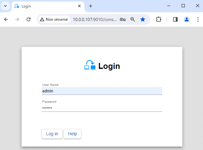
- Launch the web console in a browser on one cluster node by connecting to
http://localhost:9010. - Enter
adminas user name and the password defined during installation.
You can also run the console in a browser on a workstation external to the cluster.
⚠️ The configuration of SafeKit is done on both nodes from a single browser.
ℹ️ To secure the web console, see 🛠️ 11. Securing the SafeKit web service in the User's Guide.
2. Configure node addresses
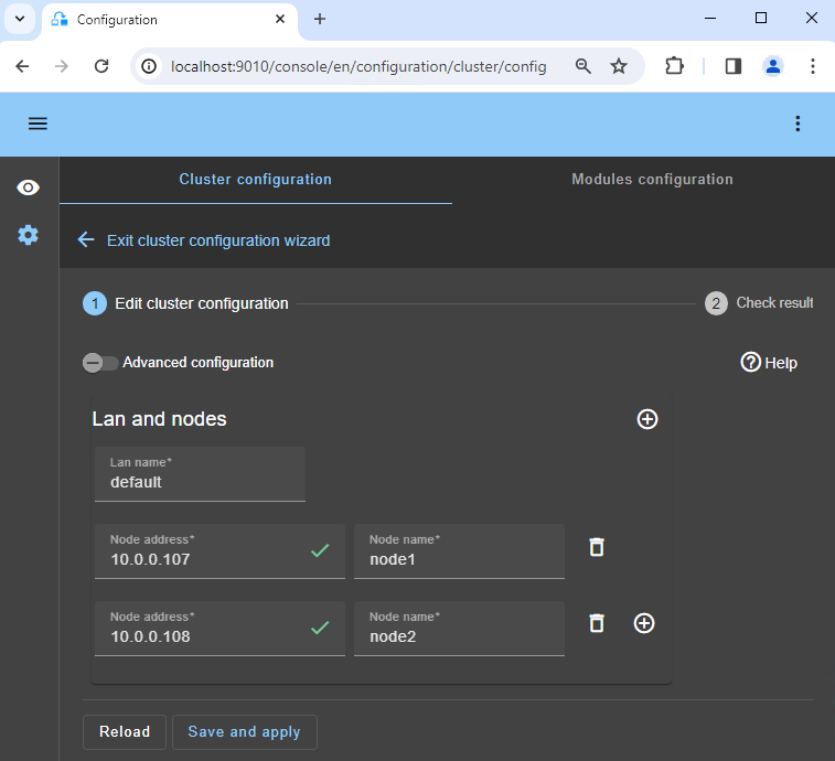
- Enter the node IP addresses, press the
Tab keyto check connectivity and fill node names. If either node1 or node2 has a red color, check connectivity of the browser to both nodes and check firewall on both nodes for 🛠️ troubleshooting. - Then, click on
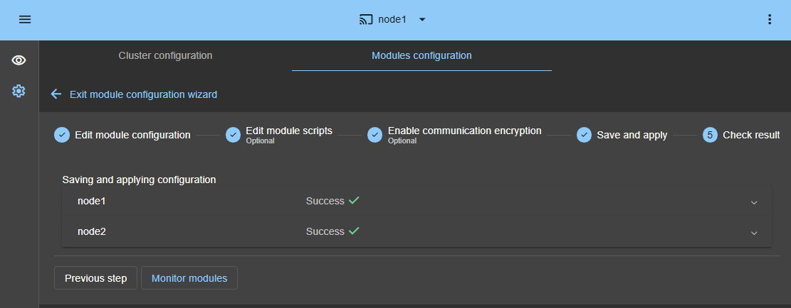
Save and applyto save the configuration. - Check the
Success✅ message on both nodes. - If the configuration
Failure❌ occurs on one node, open the ▼ accordion for that node and review the messages. Note that you can use the SafeKit AI 🤖 for assistance.
ℹ️ If you want, you can add a new LAN and nodes ( first ➕) to create a second heartbeat and a dedicated replication network.
ℹ️ If you click on Advanced configuration, the cluster.xml file is displayed. This file is automatically populated by the console and deployed on the nodes.
3. Select a module
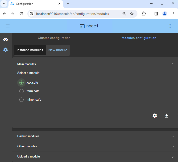
- In
New module, click on thefarm.safemodule.
ℹ️ In the blue banner at the top, 🛜 node1 represents the console connection node. This node relays requests to node2 when required.
ℹ️ The console looks for xxx.safe in the Application_Modules/generic/ directory on the connection node (node1) if you placed a module there during installation.
4. Configure the module
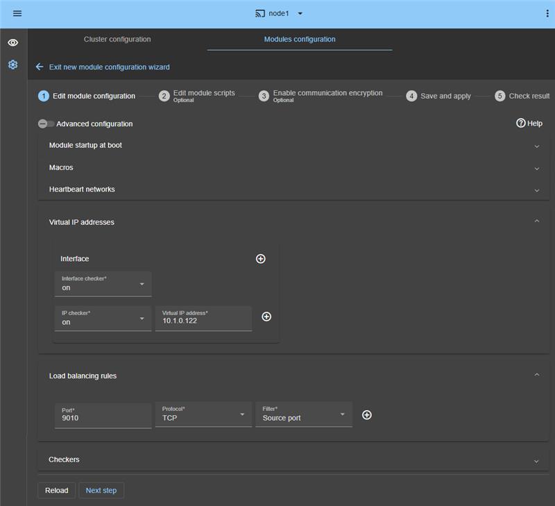
- In
Module startup at boot, choose an automatic start of the module at boot without delay. - In
Macros/SERVICES, enter the service names of your application, in the startup order, separated by commas. - In
Heartbeat networks, you should have a single heartbeat network except if you have added a LAN at step 2. - In
Virtual IP addresses, enter a virtual IP address. A virtual IP address is a standard IP address in the same IP network (same subnet) as the IP addresses of both nodes.
Application clients must be configured with the virtual IP address (or the DNS name associated with the virtual IP address). - In
Load balancing rules, set the service port to load balance (ex.: TCP 9010 in the example). - In
Load balancing rules, set the load balancing rule,Source addressorSource port:- with the source IP address of the client, the same client will be connected to the same node in the farm on multiple TCP sessions and retrieve its context on the node.
- with the source TCP port of the client, the same client will be connected to different nodes in the farm on multiple TCP sessions (without retrieving a context).
- In
Checkers, you will be able to configure checkers if needed, such as process monitoring, custom checkers, TCP, ping, or split-brain checkers.
For example, if a process name is displayed inMonitored processes/services, it will be monitored with a restart action in case of failure. Configuring a wrong process name will cause the module to stop right after its start.
ℹ️ If you click on Advanced configuration, the userconfig.xml file is displayed. This file is automatically populated by the console and deployed on the nodes with the restart scripts.
ℹ️ In a cloud deployment, you do not need to configure a virtual IP address and load balancing rules in SafeKit. The virtual IP and load balancing rules are managed at the 🛠️ cloud load balancer level.
ℹ️ When you apply the SafeKit configuration, the startup type of services is automatically set to Manual in Windows services. This ensures that services do not start automatically when the system boots, but are instead started only when the module itself is started (the same applies on Linux).
5. Edit scripts (optional)
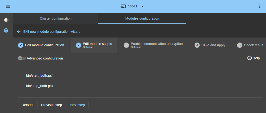
- This step is optional and can be skipped in most cases, as the restart scripts are already pre-configured to restart services defined in the previous step.
- So, click directly on
Next step. start_both.ps1starts all services in the order specified in theSERVICESlist, whilestop_both.ps1stops all services in the reverse order.- Additionally,
start_both.ps1checks the startup of each service and stops the module if any service fails to start correctly.
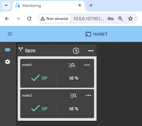
10. Wait for the transition to UP (green) / UP (green)
Node 1 and node 2 should reach the UP (green) state, which means that the start_both script has been executed on node 1 and node 2.
⚠️ If UP (green) is not reached or if the application is not started, analyze why with the module log 🖼️ of node 1 or node 2.
- Click the 🔍 log icon of
node1ornode2to open the module log and look for error messages such as a checker detecting an error and stopping the module. - Click on
start_bothin the log: output messages of the script are displayed on the right and errors can be detected such as a service incorrectly started. - Use the SafeKit AI 🤖 for assistance with log messages.
ℹ️ Note that you have a 🕒 timeline 🖼️ that can be helpful to understand what happens in the cluster.
11. Testing
SafeKit brings a built-in test in the product:
- Configure a rule for TCP port 9010 with a load balancing on source TCP port.
- Connect an external workstation outside the farm nodes.
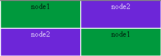
- Start a browser on http://virtual-ip:9010/safekit/mosaic.html.
You should see a mosaic of colors depending on nodes answering to HTTP requests.
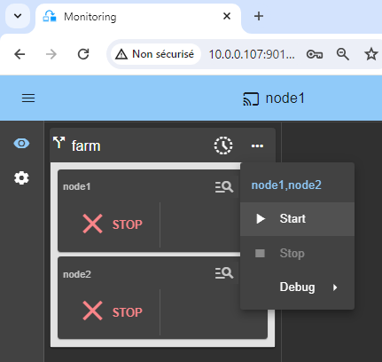
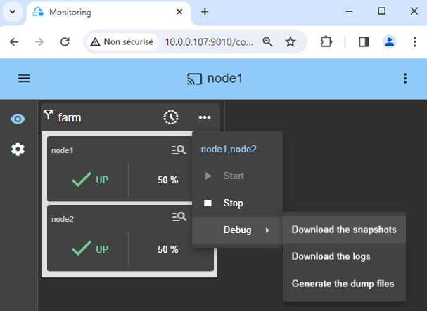
- Stop one UP (green) node by scrolling down its contextual menu and clicking Stop.
- Check that there is no more TCP connections on the stopped node and on the virtual IP address.
ℹ️ Find more details, along with videos, in the SafeKit Online Training.
12. Support
- For getting support, take 2 SafeKit
Snapshots(2 .zip files), one for each node.
Demonstration of the SafeKit farm solution
🔍 SafeKit High Availability Navigation Hub
| Resource Type | Description | Direct Link |
|---|---|---|
| Key Features | Why Choose SafeKit for Simple and Cost-Effective High Availability? | See Why Choose SafeKit for High Availability |
| Use Cases | Explore How SafeKit Ensures the High Availability of Critical Infrastructure | See All Use Cases (OEM Software, Edge Servers, SCADA, and more) |
| Deployment Model | All-in-One SANless HA: Shared-Nothing Software Clustering | See SafeKit All-in-One SANless HA |
| HA Strategies | SafeKit: Infrastructure (VM) vs. Application-Level High Availability | See SafeKit HA & Redundancy: VM vs. Application Level |
| Technical Specifications | Technical Limitations for SafeKit Clustering | See SafeKit High Availability Limitations |
| Proof of Concept | SafeKit: High Availability Configuration & Failover Demos | See SafeKit Failover Tutorials |
| Architecture | How the SafeKit Mirror Cluster works (Real-Time Replication & Failover) | See SafeKit Mirror Cluster: Real-Time Replication & Failover |
| Architecture | How the SafeKit Farm Cluster works (Network Load Balancing & Failover) | See SafeKit Farm Cluster: Network Load Balancing & Failover |
| Competitive Advantages | Comparison: SafeKit vs. Traditional High Availability (HA) Clusters | See SafeKit vs. Traditional HA Cluster Comparison |
| Technical Resources | SafeKit High Availability: Documentation, Downloads & Trial | See SafeKit HA Free Trial & Technical Documentation |
| Pre-configured Solutions | SafeKit Application Module Library: Ready-to-Use HA Solutions | See SafeKit High Availability Application Modules |